Thanks for your question! Don't worry about discrediting ACOLITE - I think you have some valid concerns, and are perhaps hitting the limits of the current implementation.
First, the approach to atmospheric correction is quite different between ACOLITE and POLYMER, whereas the former models the atmosphere and subtracts that signal from the TOA, the latter has the outputs constrained by a full spectrum water model. So POLYMER will in most cases give a realistic (looking) water spectrum. This retrieved spectrum typically matches very well with in situ measurements - if the target falls within the scope of the water model. (If it doesn't, e.g. in turbid waters, the reflectance tends to be underestimated - at least that's what we found in the Belgian Coastal Zone. Paper coming soon in RSE!)
The ACOLITE/DSF atmospheric correction finds dark targets over a certain spatial extent and fits the atmospheric path reflectance to those targets assuming no surface reflectance. There are errors inherent to this approach - there can be e.g. an overestimation of the path reflectance if there is no truly dark pixel nearby, or an underestimation if the dark pixel e.g. has a lower aerosol load, is in cloud shadows, or is impacted by sensor noise. (Due to its design the DSF is more sensitive to "negative" noise.) There could be a tendency to underestimate the path reflectance also if any of the bands have a too low top-of-atmosphere calibration. By over/underestimation of the path reflectance the retrieved spectrum will look weird, shifted down or up.
In general I see an underestimation of the path reflectance for ACOLITE, this is driven likely by the DSF not allowing negatives anywhere in the spectrum, where allowing slight negatives in the NIR for clearer waters may not be an issue. These errors tend to matter less for more reflective waters, where they are a smaller fraction of the target signal. For low reflectance waters - such as yours - these may be much more important.
In your case there seems to be an offset of about Rrs 0.005 sr-1 or around 0.016 in reflectance in the first two plots and an offset of about Rrs 0.001 sr-1 or around 0.003 in reflectance in the last plot. This seems to correspond quite well with the results for the 440 band I found here (
https://doi.org/10.1364/OE.397456), e.g. Figs. 5 and 6 (note these plots are in reflectance). Although our main intent is for ACOLITE to work well over turbid waters, I am currently investigating whether this performance at can be improved for low water signals.
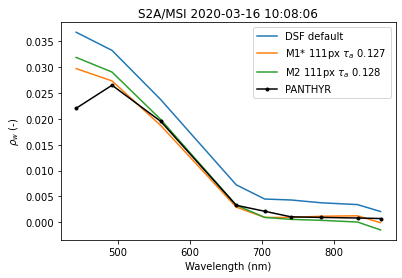
It seems like a smoothing of the top-of-atmosphere data before extracting the dark spectrum may work reasonably well to reduce some of the errors leading to an underestimation. Here are some plots from work in progress that shows the current standard ACOLITE output (blue) for a matchup to in situ data in the Adriatic Sea (black). There is a clear offset of similar magnitude to what you observed. When applying a filter at TOA before running the DSF, the retrieved reflectances are quite a bit closer (orange and green lines for continental and maritime models). This seems to indicate that a part of the underestimation could be due to noise and that a median/percentile filter can smooth out these outliers. Unfortunately in other examples (e.g. land proximity) this approach does not so well.

- ex1.png (26.67 KiB) Viewed 39303 times
- ex2.png (24.37 KiB) Viewed 39303 times
The ACOLITE performance depends also a little bit on a few other factors either from your settings (e.g. processing a ROI or using fixed/tiled processing) or from the target (e.g. is it a narrow pond surrounded by land - looking at you Biscay Pond). The processing settings can change the area where a dark pixel is found, e.g. you could use a fixed path reflectance for a crop just around Biscay Pond. The Pond has a potential issue of strong adjacency effects in NIR and SWIR (and perhaps red/green in Spring/Summer) that will be present in the output reflectance from ACOLITE. I think this is what you see in your last plot, where the reflectance goes up again towards the NIR. Since the land/vegetation adjacency effects do not look like water, POLYMER will probably be able to exclude them as it directly models the water spectrum.
A long answer... that I hope was somewhat useful!
In short, if the POLYMER results are closer to your expectations you should use them! I am not sure of the POLYMER performance for small inland waters such as Biscay Pond. In the medium term I plan to evaluate how to improve low reflectance performance for ACOLITE/DSF.
Quinten
p.s. The gains you are using do not impact these results significantly I think, but it should be noted that they are for a specific sensor+processing system so they are perhaps not directly applicable to ACOLITE.